There are many prior articles on the web about the WebRTC media path topology in a multiparty scenario. Those usually cover the basic topology of full-mesh and centralized, including MCU and SFU.
In practice, conferencing systems often exhibit complex topologies beyond this basic view. For example cascaded servers can scale to a much larger meeting or live streaming, especially when participants are geographically distributed and clustered. Separate topology for audio vs. video media paths may enable easy integration and interoperation with telephone and VoIP systems.
In this article [Open as PDF], I take a deep dive into WebRTC media path topology — understanding the benefits and tradeoffs of various alternatives — including, but also beyond, the simplified view of full mesh, MCU and SFU.
Getting started with two-party
Let's start with a simple two-party audio and video call. At first glance, a simple peer-to-peer media path is ideal. In fact, the WebRTC initiative was started with this topology: the two endpoints or browser instances with a peer-to-peer media path for audio, video and data.

The end-to-end latency is low. There is no server side media processing because there is no server in the media path. And quick feedback loop can nicely balance the client performance vs. the media quality — dynamically switching to a lower media quality when detecting higher processing load or network problem, and bringing back the higher quality when the problem stops.
Call recording in two-party
In practice, the additional requirements of multi-party, media recording and interconnectivity with VoIP systems alter the simple topology. Let's consider call recording first. When recording is desired, one of the endpoints can do the recording locally. It can share the recorded media file with the participants after the call.
Quiz 1) Which of these is a problem with call recording done at an endpoint of a two-party call?A. Asymmetric latency for the two participants causing lip-sync issue.
B. Higher processing load at the client due to double encoding.
C. Privacy violation of the other non-recording participant.
D. Higher downstream bandwidth at the recording endpoint.
The recording endpoint may need to re-encode the mixed media streams, e.g., by combining the video layouts in a single video track, and audio data in a single audio track, to store in a media file. Recording with multiple overlapping tracks per media type is possible, but is not readily playable on commodity media players. So it is preferred to record with a single video and a single audio track.
Call recording at one of the endpoints does not expose any new privacy issue beyond what is already exposed in the two-party call. However, for accountability and compliance, it may be desired or even required to have a server do the recording.
In that case, two alternatives appear: (1) either have the two endpoints send another media stream to a separate recording server, or (2) change from the peer-to-peer topology to a via-server topology of the media path. In that case, the server in the media path can do recording as and when needed.

Quiz 2) Which of these is a problem in the first alternative compared to the second?A. Higher end-to-end latency in the media path.
B. Higher downstream bandwidth usage.
C. Higher upstream bandwidth usage.
D. Double encoding of media to send out two streams.
Which alternative is better?
The tradeoff is in terms of client and server side upstream network bandwidth and end-to-end latency of the media path. The first alternative has lower server side upstream bandwidth usage and lower end-to-end latency, and the second alternative has lower client side upstream bandwidth usage - one upstream per client instead of two.
In the first alternative, the clients can avoid double encoding of the media data. It can use the same encoded media stream to send to the other endpoint as well as to the recording server. However, in some cases, double encoding may be better, to send different media data to the other endpoint and the recording server.
For example, if the recording does not need to have the same high quality media as the live real-time interaction. In that case, a lower quality, and hence lower bitrate, video stream can go from the client to the recording server. This reduces the extra upstream bandwidth usage at the client, at the cost of extra processing load due to double encoding.
Further optimization of the bandwidth can be done by active speaker detection. In that case, recording includes only the current or last active speaker's video at any time. The endpoints detect voice activity locally, and agree on who is the active speaker at any instant. Then only that endpoint sends its video, while the other endpoint avoid it, during the time that first endpoint continues to be the active speaker. When the active speaker changes, the other endpoint then sends its video, and first one stops.
For the co-ordinated active speaker detection to work, a small delay and buffering is added in the media stream sent to the recording server. This allows the system to accommodate the delay in detecting and agreeing on the current active speaker.
One problem is that every time the active speaker, and hence the video stream, changes it triggers bursty high bandwidth due to new key frames. This additional bandwidth usage may not justify the previous bandwidth savings, if the switch happens too frequently.
Going to multi-party
What happens when the third and fourth participants join the call? Continuing with the peer-to-peer topology, it becomes a full-mesh as shown below. The recording server just behaves as another participant with a difference. This recording server posing as a participant does not originate any media stream, but only consumes the streams from all the other participants.

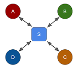
On the other hand, continuing with the via-server topology, it becomes a centralized topology as shown below. For simplicity, any bi-directional media flow is shown as a single line with bi-directional arrow.
Quiz 3) Which of these is a problem in centralized compared to full-mesh?A. Higher total bandwidth usage at the client.
B. Higher end-to-end latency in the media path.
C. Higher CPU load and processing at the client.
D. Harder to scale to a large number of participants.
Comparing full-mesh and centralized
Let's analyze and compare the bandwidth usage and processing load. Unlike the previous full-mesh topology with N(N-1) connections for an N-party call, the centralized topology has only N connections.
Clearly the centralized topology exhibits lower total bandwidth usage and lower CPU processing load at the client, whereas the full-mesh one has lower end-to-end latency in the media path, and no (or low) server processing or bandwidth. The full mesh topology does not scale well beyond a few video participants in a call, largely due to the upstream bandwidth usage at the endpoints.
In the case of full mesh, each endpoint receives the audio and video streams from all the other endpoints. It relies on the endpoint's host system to perform audio mixing, and endpoint driven application logic to display multi-party video layout, also known as video mixing.
Performance vs. quality
In general, tradeoffs in different topologies relate to (a) client vs. server processing load, (b) network usage, and (c) media quality. The processing load and network usage can be combined and treated as performance, for client and server separately. So the tradeoff is basically about performance vs. quality. Usually, there is a higher cost for higher performance. For example, high processing or bandwidth at a cloud hosted server incurs higher monthly bill.
So the goal of picking the right topology is to achieve the best quality for a given cost, or to achieve the same quality at a lower cost.
To a WebRTC application or service provider, the client side processing load or network usage does not cost anything. But those at the server side do cost real money in the cloud or data center. Thus, given a choice, the applications should keep more processing and network traffic at the client, while reducing those at the server. In the best case scenario, applications should eliminate any server in the media path. This suggests the use of the full-mesh topology whenever possible.
Unfortunately, client systems are often limited in resource capacity - and hence the maximum performance. When a client system operates at close to its peak capacity, the media quality suffers a lot. Moreover, not all clients are created equal. In a full-mesh call involving high-end PCs and low-end mobile devices, the maximum number of participants will be decided by the capability of the low-end devices. Even network constraints of wifi vs. cellular network can affect whether a good quality full-mesh of a four-party call is possible or not.
Thus, the centralized topology is more practical beyond a few participants count in a multi-party call.
What is a mixer?
In the centralized topology, the server could act as a mixer or forwarder to distribute the media streams to the participants. This is where the distinction between MCU and SFU appears. That in turn determines the actual bandwidth usage in the centralized topology. Note that both are still centralized topologies.
First, let us understand the difference between a mixer and a forwarder. What is a mixer? An audio mixer receives audio data from all the participants, and sends back mixed audio data to each participant after removing that participant's audio from the mixed stream. This is so that the speaker does not hear herself back from the mixer.
On the other hand, a video mixer (or layout generator) often combines the multiple video streams into a single video layout that includes all the received video streams. Usually, every participant sees everyone including self in the layout.
For both audio and video, the mixer receives one stream from each participant, and sends one stream back to each participant.

Inside an audio mixer
The audio mixer runs a cycle of decode, mix (add), subtract self, and encode as shown below. Because it needs access to the raw audio, it must decode, and must absorb any network jitter using a play-out buffer for each incoming stream. This process inherently causes extra latency in the media path. To reduce the latency, adaptive play-out buffer is used, and the size of buffer is kept very small in most cases.

Optimizing an audio mixer
The example above showed different participants using different audio codecs. But that is not required, and in practice multiple participants use the same codec. If the participants support the same codec, and not everyone speaks at the same time, then further optimization is possible as shown below.

Note that the last encoding step for participants C and E reuse the encoding step of A and F, respectively. Here, participants A and C are not speaking, and both support G.711, and hence, can receive the same stream from the mixer - avoiding the extra encoder step. Similarly, E and F avoid the extra encoder step too. Since the mixing step needs to remove the source audio, the optimization does not work for active speakers, B and D, at the time.
Although, WebRTC endpoints have support for common audio codec of Opus among others, the illustration here is generic even for non-WebRTC endpoints. This is useful when VoIP terminals with non-Opus codecs also connect to the audio mixer.
Cost of processing and bandwidth
What is the processing load at the audio mixer? Suppose, D, E and M are the costs of one decoder, one encoder and mixing of raw audio, respectively. If there are N participants, then the mixer processing cost is N(D+E)+M.
If the mixer limits the maximum number of simultaneous active speakers to S, then it only needs to generate (S+1) stream for encoding. This reduces the mixer cost to ND + M + (S+1)E. It still need to decode all the streams to determine which top-S participants are active speakers. Furthermore, if the active speaker detection is done at the endpoint instead of at the mixer, then the cost further reduces to S(D+E)+M+E.
What about the processing cost of a video mixer? Suppose, D, E and L are the costs of one decoder, one encoder and re-layout of raw videos, respectively. Then the processing cost is ND+L+E. Note that only one video stream is encoded and sent back to all the participants.
What is a forwarder?
Unlike a mixer, a forwarder does not need to access raw media — it does not decode or encode the media streams. The following centralized topology of a forwarder (or router) shows that it receives one media stream from each participant, and sends back N-1 streams to each participant. Thus, at each endpoint, there are one up stream and N-1 down streams. And at the forwarder there are N down streams and N(N-1) up streams.

Quiz 4) Which of these is a problem with the forwarder compared to the mixer?A. Higher total bandwidth usage at the client.
B. Higher end-to-end latency in the media path.
C. Higher CPU load and processing at the server.
D. Inability to control the displayed video layout.
Similar to full mesh, the forwarder topology relies on the endpoint system to mix audio from all the received streams. Video is similarly forwarded, and the endpoint driven application logic can display the participant's videos in any layout independent of the other participant's layout view. This is unlike the video mixer scenario, where the video layout is determined by the mixer, and is same for all the participants.
Processing and bandwidth
Compared to a mixer, the forwarder is very light weight and has low processing requirement. This is because it does not deal with encoding or decoding of the media. It also has slightly lower end-to-end latency in the media path, due to lack of decoding, encoding and related play-out buffer.
However, the forwarder has higher total bandwidth requirement due to the total number of streams, N(N-1), that it sends back to the participants. The clients also have higher total downstream bandwidth requirement.
Since ISPs typically offer higher downstream bandwidth to customers, this is not an issue with small number of participants in a call. But the client network can quickly become overwhelmed if it needs to receive media streams from all the other participants for large N.
What are MCU and SFU?
So what are MCU and SFU? They are just glorified mixers and forwarders. Some folks consider them as servers, but we will treat them as roles.
If the server is creating a combined layout with a single video stream sent to all the participants for display, it is behaving as a mixer. This is the MCU - or multipoint control unit - role of the server.
On the other hand, if the server is just forwarding the streams from each participant to all the other participants, it is the SFU - selective forwarding unit - role of the server.

A single server implementation could switch the role as and when needed. For example, if the server needs to record the call, it may need to generate a combined layout with a single video stream for recording. In that case, it may as well send the combined layout to the participants - in a mixer/MCU role. But if recording is not enabled, and there is no other need to generate a combine video stream, it could behave as a forwarder/SFU then. This avoids the expensive mixing.
Quiz 5) Where does audio mix when using an SFU?A. At the SFU server.
B. At the sender client.
C. At the receiver client.
D. SFU does not forward audio.
What happens to audio? Well, audio could still flow along with video for each participant. An MCU could include an audio mixer and a video layout mixer. An SFU forwards both audio and video from each participant to all the other participants.
Quiz 6) Which of these is true in a pure SFU scenario without any MCU?A. A client cannot send more than one media stream to the server.
B. A client cannot receive its own media back from the server.
C. A client cannot send another client's media to the server.
D. A client cannot receive its own media mixed with another client's media from the server.
Comparing MCU and SFU
In the context of WebRTC, the differences between MCU and SFU can be categorized into complexity, media quality, performance, bandwidth usage and client flexibility.
Complexity: An MCU allows a simple implementation at the client where one media stream in each direction flows over the peer connection between that client and the server. On the other hand, an SFU requires receiving multiple media streams.
This poses complex implementation choices — whether to use multiple peer connection between the client and the server, so that each connection has one media stream of one or both types; whether to create one peer connection but send multiple media streams downwards from the server to the client on the same connection; or whether to use multiple tracks of the same media stream to represent media from different participants. Furthermore, simulcast and SVC make the media flow more complex, as we will see later.
Quality: An MCU needs to work will varying network capacity of different connecting endpoints. But the MCU usually generates one media quality or bitrate for all participants, especially for video. To accommodate low end device, this often causes the MCU to pick a media quality, and hence the bitrate, on the lower end of the spectrum. This makes the quality received by every participant match that of the low end devices. Hence, the quality is relatively poor on average. Furthermore, transcoding at the mixer of the MCU causes loss of quality in both audio and video.
On the other hand, an SFU does not change the media data. It can allow different endpoints to send and receive media in different quality based on their network conditions and processing capacities. Thus, a high end machine can send high quality media, and can receive high quality media from other endpoints, as available; whereas a low end machine can send low quality media, and can selectively receive low quality media, and only from some endpoints instead of all. Simulcast and SVC further assist in quality tradeoffs of heterogeneous endpoints, as we will see later.
Performance: An MCU that includes a media mixer has higher load on the server processing due to transcoding, but lower load at the client. An SFU on the other hand, has lower server load due to lack of media processing, but higher load at the client. If the cost of the service is determined by the performance of the server, and the higher performance of server is needed to handle then higher processing load, then SFU is more cost effective for the same number of participants.
Bandwidth: We will calculate the bandwidth usage in MCU vs. SFU later. The gist is as follows: MCU bandwidth usage is O(1) at the client and O(N) at the server, whereas SFU is O(N) at the client and O(N^2) at the server. Clearly, MCU is better for lower bandwidth usage at the server, and hence lower server cost, if bandwidth is a critical factor in the server cost.
Flexibility: An MCU causes simple but rigid client behavior. The client cannot change the video display layout or selectively disable or enable certain participants' video. The display aspect ratio of the received video from the mixer is also fixed, causing the display behavior to be rigid even when the application window size or device orientation changes.
On the other hand, an SFU allows flexible client behavior in terms of video layout, accommodates heterogenous network and display capability of the individual endpoints, and allows complex endpoint driven application logic for display.
In summary, SFU wins in quality, server performance and flexibility, whereas MCU wins in low complexity, client performance and bandwidth usage. There is no clear winner in all scenarios or criteria.
When should MCU vs. SFU be used?
For many use cases, an SFU appears to perform better with video as it allows dynamic selection of media quality based on client and its network capability, and allows flexible display of video layout driven by the endpoint.
On the other hand, an MCU is better with audio centric conferencing, or those involving low bandwidth and low performance endpoints. In SFU, each client receives a separate media stream from the other participants. The client implementation relies on the underlying system to automatically mix the multiple received audio streams.
If silence suppression is not used correctly, then this wastes the received bandwidth at the client. Generally, only one or few participants will be actively speaking in a multi-party call at any time,. Hence, receiving full bitrate audio streams from all the other non-speaking participant is unnecessary. Moreover, mixing multiple streams further puts additional load on the processing capacity at the client.
In practice, an SFU implementation is often quite flexible. For example, it can allow the client to selectively pick which media stream to receive. It can even receive its own stream reflected from the SFU for self test. It allows a client to send multiple media streams if needed, e.g., from two webcams or for screen or app share. It allows audio and video to flow together or separately depending on the use case.
End-to-end encryption with SFU, not MCU
WebRTC insertable streams enable end-to-end encryption of the media data. This technique encrypts the encoded media payload, while leaving the headers intact. In a conference, only the endpoints know the decryption key, but the centralized server, MCU or SFU, does not. Hence the server cannot get access to the raw media data. This technique is useful for preventing accidental or intentional spying of media data by the application service provider.
Since headers have enough information for the SFU to forward the data correctly to the right endpoint, the end-to-end encryption works very well, even with simulcast. However, it does not work with MCU containing the mixer that needs access to the raw or decoded media to generate the mixed media data.
Although, it is also possible to make the technique work with encrypted recording of the media streams at the SFU, it it does not readily work with recording of mixed audio and video layout, or with VoIP interconnectivity to non-WebRTC endpoints that do not support the insertable streams.
What is simulcast?
We referred to simulcast and SVC a few times earlier. What is simulcast? It is an optimization technique for SFUs. It allows the client to publish multiple levels of video encoding, from high quality, high bitrate, high resolution to low quality, low bitrate, low resolution. Multiple levels are sent from the publishing client to the SFU. This is determined by the processing and network capacity of the publishing client. However, only one selected level is sent from the SFU to the client for display. This selection is decided by the processing and network capacity of the receiving client.
Thus, a high-end endpoint may publish three levels at encoded video at different media quality and resolution of 720p, 360p and 180p, with varying bitrate of, say, 1400 kb/s, 500 kb/s and 100 kb/s, respectively. The total publish bandwidth is about 2Mb/s. A low-end endpoint may decide to publish only two (or one) lower levels at 360p and 180p, at reduced bitrates of, say, 300 kb/s and 100kb/s, respectively, with a total publish bandwidth at only 400 kb/s.
A high-end endpoint may decide to receive the higher level of 720p, or middle 360p from other endpoints via the SFU; whereas a low-end endpoint may decide to receive middle 360p or lower 180p level. Thus the receive bandwidth per stream is lower than the publish bandwidth. Depending on the number of video participants in the call, the total downstream bandwidth at the client may still be higher than its publish bandwidth.
Which level to receive is determined by a number of factors at the receiving endpoint. These factors include its processing and network capacity, display size as well as the layout of the various videos it is displaying. For example, there is no point in receiving 720p level of a publisher's video if it needs to be displayed in a very small size in a multi-party video layout at the receiver side.

The above example shows high-end clients, A and D, publishing all the three levels, and low-end client, B, publishing only the two levels. The client C, which is on a low network capacity, disables simulcast and sends only one low bitrate stream. On the receive side, depending on the display size, processing and network capacity, the clients select the right level for each publisher's video. For example, B and D receive the higher level for the bigger displays of C and A, respectively, whereas A and C decide to receive the same level for all, for the same sized display of all videos.
Since the bandwidth and processing overhead of audio codecs is low compared to video, the simulcast optimization is usually not needed for audio, but can potentially be done for audio too. One example use case is when we want to support heterogeneous clients with different codecs capabilities, but also avoid transcoding load or related media quality degradation at the mixer. If some low-end clients support only G.711, and not Opus, then other high-end clients can publish both Opus and G.711 to the SFU, and the low-end clients can selectively receive only G.711 from the SFU.
The simulcast technique is codec independent, e.g., it is possible to send 720p encoded in H264, and 360p encoded in VP8. The SVC - or scalable video coding - technique, on the other hand, is codec dependent.
What is SVC?
It is a built-in optimization technique of a video codec such as H.264 or VP9. It uses multiple layers, similar to multiple levels in simulcast, to encode video in different quality and bitrate. Unlike independent levels of simulcast, the SVC layers depend on lower quality layers for decoding. That means a high end client that decides to receiver the higher layer, also must receive the middle and lower layers for correct decoding.
Although WebRTC requires and supports H.264, SVC is not required and is not part of the WebRTC specification. Existing browsers may not support SVC in H.264. The emerging VP9 and H.265 efforts include SVC though. Nevertheless, the optimizations are good for scaling a video conferencing systems to a large number of participants and a diverse set of capabilities of endpoints and their networks.
A benefit of SVC compared to simulcast is that the layers work seamlessly without additional overhead or complexity in signaling, and are usually self contained within the video codec implementation. It can also achieve more optimization in bandwidth and processing load. A benefit of simulcast over SVC, as mentioned before, is that it is codec independent.
Both simulcast and SVC are intended for centralized topology, where the endpoints publish multiple levels or layers, and consume only a subset. Modern SFU implementations are compatible with simulcast, and are increasingly getting compatible with SVC. In our discussion, we will assume the use of SFU topology when simulcast is considered.
Call recording with MCU and SFU
I mentioned earlier that the requirements of call recording and VoIP interconnectivity often alter the simple topology of a call. An MCU can readily implement call recording, since it already has the mixed media stream for both audio and video. An SFU has two choices to implement recording - either it can dump each received media stream from each participant separately and independently, or it can include a mixer to create and save a mixed media stream for audio and video.
In the first case, the playback of call recording is more complex, and requires a dedicated playback app. Existing media players often assume non overlapping tracks for each media type. Hence, the recording cannot just be sent as a single recorded media file for the call with separate overlapping tracks for each participant. Thus, this often requires a dedicated and custom playback app.
In the second case, the SFU performance suffers as it now includes the expensive media processing too. Although, video decoding is a lot faster than encoding, it needs to be done for each received video stream. This affects the performance as the number of call participants increase.

Since call recording does not need to be done in real-time, the multiple media streams' data stored by the SFU can be merged or mixed offline. This can be done using an offline mixer, or tools like ffmpeg.
Call transcription
Recent advances in transcription of voice to text also need access to raw audio data. Transcription uses the same topology as call recording. Moreover, a real-time transcription can be done readily on separate audio streams, because there is no strict requirement for transcribing only the mixed audio stream.
In fact separate transcription is often desired, so that the transcribed text can easily identify the speaker. Speaker or voice activity detection may still be needed to save cost by removing silence or non-speaking audio, if the cost of transcription depends on the length of audio stream to be transcribed, rather than the length of the detected spoken text.
VoIP interconnection with MCU and SFU
A VoIP terminal often has a simpler implementation of media streams. There is only one audio and at most one video in each direction. Requiring a VoIP terminal to receive multiple media streams from the SFU is not practical. Many VoIP terminals are audio-only, so that simplifies the situation a bit, as discussed below.
How does such a VoIP terminal connect to a full mesh or an SFU topology, without using the explicit MCU? One approach is to use a gateway which connects to the VoIP terminal on one side, and acts as a participant in the SFU topology on the other side. In the case of full mesh, the gateway becomes a participant as well. It turns out that the MCU and SFU combination described later can act as such a gateway.

The first topology shown above uses an MCU with a simple gateway, that poses as one client to the MCU for each connected VoIP terminal. The gateway transparently forwards media between the VoIP terminal and the MCU without any mixing. This works well if the gateway is located close to the MCU.
However, if the gateway is on a separate machine, then it could causes multiple redundant media traffic from the MCU to the gateway. A variation of this topology forwards each VoIP stream to the MCU, but receives only one mixed stream from the MCU, which it then forwards to all the VoIP terminals. Such cascaded mixers will be described later in the article.
The second topology requires the gateway to have a selective forwarding function, so that it can receive all the media streams from the regular clients A-D as well as VoIP terminals P-Q, select one stream at any time based on the active speaker detection or other criteria, and forward that to the VoIP terminals. It also forwards all the media streams received from the VoIP terminal to each of the regular clients. The SFU forwarding function is basically split between the two components now.
The third topology involves both a forwarding and a mixing function in the gateway. In that case, the gateway sends a media stream mixed from all the clients' streams to the VoIP terminal, and a mixed media stream from the VoIP terminals to the SFU. A variation in this topology could allow mixing only for delivering media to the VoIP terminals, but keep separate media streams from the VoIP terminals to forward to the SFU.
Complexity of media flows
Such a gateway implementation is not trivial, since it needs to include a modified MCU role. Let's assume that the VoIP terminal is audio-only, and does not care for video. The gateway must mix audio coming from all the other participants to send to the VoIP terminal. But in the reverse direction, it must decide either to forward the audio from the VoIP terminal as is to the SFU, or to mix all the audio from the VoIP terminals to send as a single stream to the SFU.
What if there are multiple VoIP terminals that connect in the call? Now the gateway's media flow becomes more complex. It must mix all audio and subtract the audio of the VoIP terminal before sending back audio to that VoIP terminal, similar to an MCU. But when sending audio from the VoIP terminal to the SFU, it must generate separate audio streams - one per VoIP terminal.
The SFU implementation may have restrictions, such as to receive only one audio stream from each participant. In that case, the gateway poses as multiple pretend-participants to the SFU - one per VoIP terminal. But then the SFU will send back audio streams multiple times from the other participants to the gateway - one set to each pretend-participant. To avoid that, it must mute itself from receiving any streams from all-but-one pretend-participants. And it must correctly use and mix the received streams for that one pretend-participant, before sending to the VoIP terminal, similar to an MCU. As you can see, this becomes quite complex.
If the MCU role is not to be used at all, then the gateway must select one of the video streams, e.g., based on the current or recent active speaker, to send back to the VoIP terminal, which is capable of receiving only one video stream. This is similar to the second topology where gateway has the forwarding, but no mixing, function. Such selective video forwarding is readily available in the SFU role anyway.
Processing and bandwidth at the gateway
The resource consumption at the regular clients, A-D, and servers, MCU or SFU, are the same as that described earlier -- MCU and SFU with O(N) and O(N(N-1)), respectively, and their client with O(1) and O(N), respectively. The VoIP terminals have a single media stream constraint, and hence, also have O(1) processing load and bandwidth usage. The gateway, on the other hand, behaves differently for different topologies.
In the first topology, the gateway requires O(P) processing and bandwidth, if P is the number of VoIP terminals connected via the gateway. In the second and third topologies, the gateway requires O(N). However, since the third topology uses a mixer, the absolute processing load will likely be much higher in the third topology compared to the second one.
Which of the three topologies to use?
If MCU is already used as the core of the conferencing system, then the first topology is the natural choice. However, if the core of the conferencing system is based on SFU, then the decision to pick the second or third is based on the relative number of VoIP terminals versus regular clients. If it is expected that there will be too many VoIP terminals, such as phone callers, then using a built-in mixer of the third topology becomes more efficient. But with only a few VoIP terminals are expected in a call, the second topology based on forwarding, without any mixing, may be more efficient.
Without a real mixer in the second topology, it may become challenging to accurately detect active speaker, to send the right audio stream to the VoIP terminals. In that case, using a mixer only for audio, but not for video, may be useful. We will explore such a scenario soon.
MCU vs. SFU or MCU and SFU
Often times, the added cost of such complexity of the topologies described above may not be worth the benefit. An alternative is to separate the audio and video paths, as we describe next, so that the audio is sent to MCU and the video to SFU. If the VoIP terminal is capable of video too, then it can receive the combined layout that the MCU has prepared for recording. Incorporating video sent by the VoIP terminal is not trivial as we will see.
For call recording and VoIP interconnectivity, the SFU role often exposes more complexity, and the MCU role works better. However, letting the whole system's performance suffer due to a few VoIP terminals is not desirable. Hence, it is useful to have MCU and SFU roles working together for a single call. If a gateway is employed to interconnect with a VoIP system, then such a gateway needs to deal with both SFU and MCU roles.
What is a split topology?
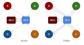
Can both MCU and SFU be used together? One option is to separate the audio and video streams, and use MCU for audio and SFU for video. Let's call this a split topology. What are the benefits of this split topology?
Firstly, audio codecs have lower processing overhead than video. Hence, the performance is less affected if only audio is on MCU. The video, which could contribute to more processing load at the mixer, is not sent to the mixer, and is not mixed. Secondly, the layout flexibility benefit of SFU is largely driven by video. This remains true in this split topology. Thirdly, accommodating audio-only VoIP terminals via an MCU is easier.

The audio stream over MCU allows heterogeneous codecs support at the endpoint, by doing transcoding at the server. This helps particularly with VoIP interconnection, where VoIP terminals may not all have the same codecs as WebRTC.
In the context of WebRTC, the implementation can choose whether to use one peer connection between the client and server, and send various media tracks in separate streams on the same connection; or whether to use a separate peer connection for each stream. As mentioned before, keeping the audio and video from the participant's client to the server in the same media stream as separate media tracks can allow media synchronization at least for a part of the media path.
Processing and bandwidth
Audio over MCU also allows scaling to large audio conferences from the client perspective. This is because each client's receive bandwidth and processing load is O(1), independent of the number of participants. As mentioned before, audio codec needs lower CPU processing than video, so server CPU usage of O(N) = aN has lower constant, a. Further optimization is possible as described earlier by limiting the maximum number of active speakers.
The video stream over SFU avoids quality degradation and server scaling limits due to lack of video transcoding at the server. Compared to MCU, the SFU's upstream bandwidth is higher, O(N^2), at the server, and downstream bandwidth is higher, O(N), at each client. However, clients on low network capacity can select only a few of the many video streams to receive. This applies particularly to large conferences. For example, in a 200-party video call, each participant will likely view only a small subset of, say, 25 or 40 videos at any time, and need to receive only those number of video streams from the SFU.
A client does need higher CPU processing of O(N) = dN for decoding, compared to O(1) = e for encoding. Decode processing load is much lower than encode. So it is not a big issue in practice, when combined with selective video receive logic.
The client and server bandwidth optimization is possible by reducing the number of videos displayed at each client. The simulcast and SVC optimization technique, that work with SFU, continue to work for video over SFU in the split topology. Top S active speakers may be detected to determine whose videos to display in a reduced layout at any instant.
Quiz 7) Which of these is a problem with audio on MCU and video on SFU?A. One server implementation with both MCU and SFU roles is required.
B. Audio and video can go out of sync causing lip-sync issue.
C. Sometimes a participant's audio is played without her video.
D. It scales to support more audio participants than video due to bandwidth.
Other benefits and limitations
This split topology of audio on MCU and video on SFU is quite flexible. Typically, in a large conference, there are more audio clients than video, because some participants join with audio-only, whereas others join with audio and video. The split topology can scale to support such scenarios, due to lower bandwidth usage of the audio participants.

Due to display limitation of showing too many videos at once, the split topology actually supports the desired scaling where there are more audio participants than video. Moreover, if the MCU and SFU roles are deployed as separate servers, then they could be scaled independently.
One problem with the split topology is that audio and video streams may go out of sync causing the lip-sync issue. In particular, media path for audio may have additional delay due to the mixer and play-out buffer.
It is not trivial to use the existing RTCP controls to synchronize the audio and video. This is because the audio received at the endpoint is a mix of all the other participants' audio, whereas the video received is separate from each individual publishing participant.
Quiz 8) Which of these does not help in mitigating the lip-sync issue, assuming audio on MCU and video on SFU?A. Keep MCU and SFU co-located on the same machine.
B. Keep play-out buffer delay at MCU to be very low.
C. Send one stream with audio and video from client to server.
D. Include mixed audio in each video stream from server to client.
Some steps can be taken to mitigate the potential lip-sync issue. For example, the play-out buffer at the mixer can be forced to be very low. The MCU and SFU roles may be co-located on the same physical machine, reducing the differential effect of network on delay and jitter.
The client can send one stream with both audio and video to the server, and let the server determine how to apply MCU and SFU roles for the two media tracks of that stream. This will keep the media stream in sync, at least from the client to the server.
Separate MCU and SFU processes
This is readily doable if the same server process includes both MCU and SFU as shown previously. However, if the MCU and SFU roles are implemented as separate server processes, even if on the same machine, then only one of them will terminate the synchronized stream with audio and video tracks from each client.
Since SFU is more flexible than MCU, in terms of how many streams are allowed to/from each client, it is better to have the client's peer connection with the SFU process, instead of with the MCU process, and let the SFU process selectively forward the client streams to the MCU for mixing and/or recording as needed. The topology then becomes as follows.
Call recording
How does recording work in this split topology? The MCU already generates the mixed audio and video stream, and hence, can do the recording using the mixed streams. The audio path is bidirectional, between the client and SFU and then between the SFU and MCU. The video path is unidirectional from the SFU to MCU, so that the MCU can record the participant's video, but the participant does not need the mixed video layout back from the MCU.
Thus, the SFU poses as a client to the MCU on behalf of each participant, forwards the participant's audio and video to the MCU, but receives only mixed audio, not video, from the MCU to send back to the participant. At the same time, the SFU forwards the video stream from each participant to all the other participants. If recording is not enabled, then the SFU does not need to forward the video to the MCU. But the audio still need to be forwarded, so that the MCU can mix the audio in the split topology.
VoIP interconnection
How does it interconnect with a VoIP system? A modern implementation of the endpoint is perfectly capable of receiving multiple media streams. However, a low end device such as a telephone or VoIP terminal usually handles only one media stream in each direction.
Interconnecting such VoIP terminals to an MCU topology is straight forward. It is still possible to connect to the MCU via a gateway, as we discussed earlier. This gateway is needed to translate the signaling and media path wrappers/headers between the VoIP protocols such as SIP on one side, and WebRTC on the other.
The gateway does not need to modify the media data, if the VoIP terminal also supports the same codec. It also does not modify the media path topology. Hence, for simplicity, we depict the VoIP terminals connected to the MCU directly, and hide the gateway below.

When the MCU and SFU are in the same server process, the split media path topology is shown above. An audio-only VoIP terminal can connect to the MCU directly, so that it has one audio stream in each direction of send or receive. When the VoIP terminal is capable of video, and the video is over SFU, we let the VoIP terminal connect to the MCU first for video.
However, in that case, the MCU must also forward the video stream to the SFU, as if it is a client of the SFU. That will allow the SFU to send the stream to all the other participants. Care must be taken so that the SFU does not send any stream coming from the MCU back to that MCU, even though the MCU poses as a separate client on behalf of each video capable VoIP terminal.
The split topology also extends to other low end devices that are not capable of handling multiple video streams due to their limited processing or network capacity. For audio, each participant sends and receives one stream with the MCU. For video, the VoIP terminals, P and Q connect to the MCU, whereas the other regular participants, A-D, connect to the SFU.
Thus, in the example above, the regular clients send one video stream to the SFU, and receive N-1=5 streams from the SFU, one for each of the other participants. The video streams from the VoIP terminals, are received by the MCU, and forwarded to the SFU, to send to all the other regular clients. As before, the video streams from the regular participants as well as the VoIP terminals are all mixed in a layout that is then used for recording, as well as is sent to the VoIP terminals only, but not to the regular participants.
Revisiting separate MCU and SFU
Unlike the previous example, if the MCU and SFU are in separate server processes, then the following shows the media path topology. This requires the MCU to be modified to allow forwarding video as is from the VoIP terminals to the SFU, without mixing. The added complexity at the MCU makes the system prone to problems.

Note the number and direction of video streams between different components. In particular, the VoIP terminals, P and Q, have one bi-directional video stream with the MCU. The MCU sends their streams as is to the SFU, showing two such streams from MCU to SFU. The SFU receives one stream each from the regular clients A-D, and forwards them to the MCU as well. Furthermore, the SFU forwards the streams from each regular client A-D to all the other regular clients A-D, as well as the streams from the VoIP terminals, P and Q, via the MCU, to the regular clients A-D. Thus, it shows five streams from the SFU to the regular clients.
Alternative topology
An alternative to the modified MCU, is the modified SFU. Here, the VoIP terminals connect to the SFU directly (actually via a gateway as before). The SFU delivers all the streams to the MCU for mixing, and receives the mixed streams from the MCU, and selectively forwards the received mixed video stream back to the VoIP terminals, as described next. In this case, the SFU becomes the controller (master) and the MCU becomes the controlled (slave), to perform mixing of the streams on demand.

The SFU forwards all the audio streams to the MCU for mixing, and receives the audio from the MCU to be forwarded back to the participants, both regular clients and VoIP terminals. For video, the SFU still forwards all the streams to the MCU. But it receives only the mixed streams needed for the VoIP terminals, which are then forwarded to the VoIP terminals. Thus, each VoIP terminal receives one mixed video layout.
The example above shows two video streams from the MCU to the SFU. But only one may be enough, if all the VoIP terminals show the same video layout. To further reduce the load on the MCU, especially when recording is not enabled, the SFU may decide to select one of the video streams to send to the VoIP terminals, P and Q, based on the active speaker detection. This topology clearly benefits from the master-slave arrangement of the SFU and MCU roles.
Revisiting processing and bandwidth
Let us derive some scalability and performance numbers. A single MCU or SFU has limits on how many clients it can accept, due to its processing or network capacity. How does the processing and network usage change based on the number of connected clients?
Suppose there are n participants with audio, out of which N participants also have video enabled, such that N is usually smaller than n. Let d and e be the processing needed to decode and encode audio, respectively, and D and E needed to decode and encode video, respectively. Let s be the maximum number of active speakers, such that s is much smaller than n and is usually a small constant, like 3 or 5.
Let m be the processing for mixing, adding and subtracting one audio stream, and M be the processing per video for creating the mixed video layout. Then the processing at the MCU is given as nd + sm + (s+1)e + ND + NM + E. There are some other terms such as for receiving and sending media, but those can be accommodated by adjusting d and D accordingly.
This expression assumes that the (n-N) audio-only participants do not send and do not receive video. If the audio-only participants also receive video from the server, then the expression could remain the same if d, instead of D, is adjusted to accommodate the processing cost of sending the video from the server.
Assuming that all the participants use the same media codec and bitrate, b and B, for audio and video, respectively, and W for mixed layout video from the MCU to the participants, then the downstream and upstream bandwidth usage at the MCU become nb + NB and nb + NW, respectively. The upstream bandwidth increases to nb+nW if the audio participants also receive video from the server.
Let f and F be the processing for forwarding audio and video, respectively, from one client to another at the SFU. Then the processing at the SFU is n(n-1)f + N(N-1)F. Generally, f, F, m or M are a lot smaller than d, e, D or E. Also D is usually much smaller than E.
The downstream and upstream bandwidth usage at the MCU are nb + NB and n(n-1)b + N(N-1)B, respectively. The upstream bandwidth increases to n(n-1)b + N(n-1)B if the audio participants also receive video from the server.
Another alternative topology
Another topology for VoIP interconnectivity is shown below. The previous examples assumed that the non-VoIP system is the core of the conferencing, whereas the following topology assumes that the VoIP conferencing already exists and is mature. It attempts to keep VoIP as the core, and attaches the regular clients via SFU to that core as shown below.
This resembles an earlier one discussed in the context of VoIP interconnectivity, where the gateway includes both the forwarding and mixing functions. The media streams also flow similar to that one.
The MCU on the left belongs to the VoIP system, whereas the one on the right is attached to the gateway and works closely with the SFU. The SFU on the right poses as a single participant to the MCU on the left, using a gateway.
If the VoIP system on the left is audio-only, then the gateway and MCU on the right only include a low-cost audio mixer, and no expensive video mixer. If the VoIP system on the left includes video, then the SFU and gateway on the right can decide whether to do selective video forwarding or to generate a mixed video layout. In any case, the SFU receives only one mixed video stream from the MCU on the left, and distributes it to all the other regular clients, A-D.
Such topologies are seen in practice for incremental deployment of emerging advanced video conferencing systems on top of existing traditional VoIP conferencing. The processing load and bandwidth usage are already analyzed earlier for a similar topology.
Processing load at MCU vs. SFU?
Although an MCU's processing is O(n) and SFU's is O(n^2), the absolute value or constant factor for the MCU is much larger than that for the SFU. Thus, given the same hardware specification, the MCU will reach the limit at a lower number of participants than the SFU, especially with video enabled participants because video decode and encode is more expensive than audio.

As seen in the previous expressions, there are many factors that affect the processing and network usage at the server, and hence the number of clients it can support. In practice, these factors are adjusted to arrive at some "capacity" of the server. For example, a server specification may say that it supports up to 200 participants on audio, with at most 40 sending video at any time; or that it allows 100 video participants , but each participant can see only up to 25 videos at a time.
Horizontal scaling of MCUs
Distributing load among multiple servers using horizontal scaling is possible for both MCU and SFU. For MCU, this is usually done for the number of calls - assuming each call is roughly with a similar number of participants. In practice, the distribution of participants per call is skewed, such that a few calls have too many participants, and many calls have only a few participants.
One option is to pick a less loaded MCU server based on the expected load of the new call. In some cases, the expected load is known ahead of time based on how many people the meeting invite was sent to. In other cases, expected load is not known ahead of time. In that case, dynamically scaling an ongoing call beyond the capacity of a single server is problematic. Cascading can solve this, as described later.
The two examples shown below, one with many small party calls, and the other with one large party call, have similar load on the server, because the total number of participants is same. The linear, O(n), processing load at the server can be used to distribute the load among multiple MCU instances.

In particular, a balanced system will be the one where all the MCU instances have roughly similar number of connected participants, irrespective of the number of calls hosted on that server. Note that this is not true for SFU, due to its non-linear, O(n^2), processing load at the server.
Horizontal scaling of SFUs
Due to the quadratic, O(n^2), processing load at the SFU, balancing the load among multiple instances is not trivial, unlike the MCU. For example, if one instance hosts a hundred-party call, with a hundred connected participants, and the other instance hosts hundred ten-party calls, with a thousand total participants, the load will be roughly balanced between the two instances, even though the second has ten times more participants then the first.
The following illustrations show twelve participants connected in four separate calls in the first, in a single call in the second, and only six participants in a single call in the third. Only one connection per call is shown for each stream to avoid clutter. The number of down streams at the server is same as the total number of participants irrespective of the calls. But the number of up streams at the server is quadratic - the first one has the sum of N(N-1) for all the four calls, which comes to 2x3 + 3x4 + 1x2 + 2x3 = 26. The second with one call has 11x12=132. The third with only six participants in one call has 5x6=30 up streams, which is comparable to the first's 26 up streams with twelve total participants.

Multiple SFUs per call
SFU can be easier to scale horizontally. Although it is natural to think of a single SFU, like a single MCU, handling all the participants in a call, it is not really required, unlike MCU. One option is to have different participants of the call use different SFU instances to forward their media to other participants. This allows larger number of participants in a single call, spanning multiple SFU instances.

The above example shows the first two participants of the call connected to the two separate SFU instances. As more participants join, they connect to one of the two SFU instances. The basic expression about the number of down streams and up streams at each SFU instance follows the same logic - down streams count depends on the number of participants publishing to that SFU, and for each such publisher, the up streams count depends on the number of participants in the call that publisher is part of.
Multiple layers of SFUs
The upstream count at the SFU is O(N^2). This can be reduced by using multiple layers of SFUs. Consider the following example with six participants. All the participants send their media streams to the primary SFU in the first layer. The primary SFU splits the received streams almost equally to the two secondary SFUs in the second layer. The second layer SFU then fans out their streams to all the participants.

The downstream count at the first layer SFU remains at N=6, but the upstream count changes from N(N-1)=30 to only N=6. For each of the second layer SFUs, assuming there are M=2 such second layer SFUs, the downstream count is N/M=3. And the upstream count is N(N-1)/M=15. Each of the endpoints still has 1 upstream and N-1=5 downstream count, similar to the single SFU case.
When the number of second layer SFUs is same as the number of participants, M=N, then each second layer SFU has only N-1=5 upstreams. It is not hard to see that if the number of layers is changed from 2 to log(N), then the upstream count per SFU can be kept at O(N). Consider N=256, and each subsequent layer quadruples the number of SFUs. Then it needs four layers. This is because log4(256) in base 4 is 4. The second layer has 4 SFUs, third layer as 16 SFUs, fourth layer has 64 SFUs. Each SFU in subsequent layers, one to four, has downstream counts of 256, 256/4=64, 256/16=16 and 256/64=4, respectively. The upstream counts are 256, 64x4=256, 16x4=64, 4x256=1024, respectively. This fan out topology causes the last layer SFU to have the maximum upstreams count of kN where k is the fan out factor of 4 here.
The first layer can also have multiple SFUs to scale further to very large conferences. For example if N=2048, and each SFU has a maximum limit of up to 1024 streams, then at least two SFUs are needed in the first layer. Each layer adds towards the end-to-end latency on the media path. Hence, M should be kept small when the end-to-end latency is desired to be low.
Unlike the previous fan out topology, which punishes the last layer SFUs, an alternative is possible, which has a more balanced set of SFUs. The fan out is optimized to balance the number of streams more evenly. To understand this graph problem clearly, consider the media stream from one sender to all the receivers. If each SFU has a maximum limit of S number of upstreams, then how many steps or layers does it take to fan out 1 sender to N receivers? (actually N-1 receivers, but for simplicity, let's go with N). The answer is P=logS(N), i.e., logarithm of N in base S. And how many nodes are needed for such distribution? The answer is the series sum of 1+S+S^2+S^3+... up to the number of layers. This is (S^P-1)/(S-1)=(N-1)/(S-1). For example, if N=256 and S=4, then there are 85 nodes over 4 layers. This is for one sender. Thus for N senders, the system needs a total of N(N-1)/(S-1) nodes or SFUs.
As an example, suppose each SFU has a limit of 1 thousand streams, and there are 1 million participants. Then the system will need about one billion SFUs. Not quite practical, is it? An it should not be either. A participant is not expected to receive 1 million streams from the other participants.
A practical but extreme example could be where there are 1 million participants, but each participant can receive only say up to a hundred streams at any instant. How is the calculation adjusted in that case? Consider the simplified case where each sender's stream goes to about a hundred viewers. In reality, this will not be as simple, and a few senders will be received by almost all viewers, whereas many senders will not be received by any viewer.
In the simplified case, since each SFU can have up to 1 thousand streams, it can handle 10 senders. Thus, the system needs 100 thousand SFUs to serve 1 million participants. And about 2 thousand SFUs to serve 20 thousand participants.
An extremely skewed case is where the top 100 participants are viewed by all the 1 million participants, and all the other participants are not viewed by anyone. Using the previous analysis, each of those senders needs (N-1)/(S-1) or about 1 thousand nodes or SFUs to fan out to N=1 million participants, where node fan out limit is S=1 thousand. Hence, for 100 senders, it will need 100 thousand SFUs. And about 2 thousand SFUs to serve 20 thousand participants. These numbers are similar to the simplified case analyzed previously.
Let's generalize the expression for the number of SFUs needed to serve N participants, where each participant can receive only up to R streams and has a maximum fan out limit of S. Assuming large N and S, this results in approximately RN/S instances of SFUs.
Peer-to-peer media distribution
When such network is created without the hosted SFUs, but with endpoint driven SFUs, such as in the application level multicast scenario, then the fan out factor is much lower. As S is reduced, the number of nodes needed for distribution increases. Fortunately, with application level multicast created by serverless or peer-to-peer network, the nodes count naturally increases as the participants count increases. This provides implicit scalability, albeit at the cost of higher latency due to the multiple steps or layers in the media stream distribution.
Using an MCU with multi-layer SFUs
To reduce the number of SFUs, a network of MCUs may be used in the initial layers. An example is shown below with two senders (or speakers) limit. The topology behaves as SFU for senders, but MCU for others. For a large conference, the streams from the top-S senders are mixed at an MCU, and then the single mixed stream is distributed to most of the other 1 million participants, using a network of multi-layer SFUs.

The top-S senders, on the other hand, exchange the media streams using the SFU directly, instead of consuming from the MCU. It may need multi-layer SFUs and/or multi-layer MCUs among the S participants, if S is also large. In that case, 1 thousand SFUs and a few MCUs will be enough to serve 1 million participants with at most 100 active senders at any time.
Multi-layer SFUs in these topologies are examples of cascading. Distributed cascading can further increase the number of participants and improve bandwidth usage as described next.
How to cascade MCUs?
To scale a multimedia call beyond the capacity of a single MCU or SFU, cascading is used. Cascading is a very old concept, from the early days of conferencing. The early ideas on multicast and application level multicast for large scale multimedia conferencing solved many theoretical problems in scaling, that are now renamed or termed as cascading.
Let's start with MCU cascading. Consider the following example topology with three cascaded MCU instances. There are one primary and two secondary MCUs, connected hierarchically. Each MCU performs similar audio processing described earlier - decode, mix-minus-one, and encode - for audio. It also performs similar video layout mixing on the received video streams. Each flow shows the media stream sent or received on that flow.

Depending on the number of cascading layers, audio and video may be transcoded multiple times, further degrading the quality. This can be mitigated by using raw audio on the inter-MCU streams, at the expense of higher inter-MCU bandwidth usage. However, using raw video on the inter-MCU streams in quite inefficient due to its very high bandwidth.
Previously described active speaker based optimization, by limiting the maximum number of active speakers, is harder to achieve. This is because determining the top-S active speakers across all the MCU instances in a distributed manner is not easy. Nevertheless, pre-selecting video based on active speaker may mitigate the video issue.
The video tile layout is created based on the number of received video streams. However, each video stream may itself be a tile of other streams, causing nested tiles in layout. The number of nested videos in a stream may be used to determine the tile layout, e.g., by giving more space to the video stream containing nested videos in the tile.
Quiz 9) Which of these is not a possible video layout in the previous example of the cascading topology?

The video layout in cascading will keep the videos of the participants together if those participants are directly connected to the same MCU instance. Thus, D and E will be together, and so will C and F. Thus, only the option C above does not show the right layout where D and E are together, as well as C and F are together. It is easy to see how option A and D are possible. Since A and B are directly connected to the primary MCU instance, which also receives tiled video from secondary instances for D+E and C+F, it is possible to create option B above.
Quiz 10) Which of these is not correct for three audio-only cascading MCUs with total N connected participants?A. Each MCU must connect directly with roughly N/3 clients.
B. Each end-to-end audio stream can be decoded and encoded exactly once, reducing the number of transcoding steps.
C. Bandwidth at the MCU depends on the number of other MCUs and clients it is directly connected with.
D. All the three MCUs can connect with each other in full mesh to exchange mixed audio to reduce end-to-end latency.
Although load balancing is desirable in a cascading topology, it is not a requirement. Even though the previous example showed hierarchical cascaded MCU instances, it is possible to have all the MCU instances be connected in full mesh. In that case, each instance must carefully curate the stream sent to the other instance, so as to include audio of only the directly connected participant when sending to the other instance, and to not include the audio received from another instance.
Quiz 11) Which of these is correct and is a benefit of the cascading MCU compared to a single MCU?A. Shorter network paths allow quicker recovery of packet loss, and quicker congestion detection.
B. Client needs lower CPU since many streams are decoded and mixed at other MCUs not directly connected to this client.
C. The conference size as the number of participants can be scaled exponentially O(2^M) with the number of cascading MCUs, M.
D. Total MCU bandwidth cost is reduced by using spanning tree topology among cascading MCUs.
How to cascade SFUs?
Let's see how SFU cascading is different from MCU one. Consider the following topology with three cascaded SFU instances. Here, the audio and video data flow together in the same media stream. And there are multiple streams flowing in various media path hops as marked below.

In the spanning tree topology shown above, there is no cycle in the SFUs connection topology. Each SFU node forwards all the streams from one side of the tree to the other. Some end-to-end latency may be very high due to the long hop-distance of the spanning tree topology.
To reduce the latency, a full-mesh topology among the SFU instances is shown below. Here all the SFU instances are connected to each other. Each SFU node forwards only the streams of its direct clients to all the other SFU nodes, and forwards the streams of all the other SFU nodes and all the other direct clients to each of the direct client. End-to-end latency is optimized to three hops only. Inter-SFU bandwidth is also reduced on a pair-wise basis. This is useful for large scale interactive meetings.

Quiz 12) Which of these is a problem for the cascading SFUs compared to a single SFU?A. Client has higher received bandwidth requirement.
B. Each SFU has higher send bandwidth requirement.
C. Total SFU bandwidth cost is higher due to inter-SFU links.
D. CPU processing load is higher at the server.
Processing and bandwidth
Let's calculate the processing cost and bandwidth usage at each SFU instance in the cascaded topology. Suppose, each receive stream costs R, and send stream costs S. Suppose there are N clients and M servers, and each server has roughly C = N/M direct clients. In full-mesh, each SFU instance receives stream from every client. It sends N-1 streams from all other clients to each of its C directly connected clients. And it sends C streams of its directly connected clients to all the other SFU instances. Thus, the total cost becomes NR + (N+M-2)(N/M)S. Suppose each stream bandwidth is B. Then the bandwidth requirement at each SFU instance becomes: receive NB and send (N+M-2)(N/M)B.
Additional considerations with cascading
Previously, we discussed the split topology with audio on MCU and video on SFU. Can this work with the cascaded topology? Suppose audio on MCU and video on SFU media paths are cascaded in separate logical topologies, even if the physical system may have co-located SFU and MCU in each node. Due to the varying latency in MCU vs. SFU media paths, getting proper lip-sync is extremely difficult. So such an option is not practical.
Previously, we also discussed simulcast and SVC optimizations to reduce bandwidth and processing load at the server and receiving clients. Can this work for the cascaded topology? For simulcast or SVC to work properly, the inter-SFU streams must include all the simulcast levels and SVC layers. That will allow the clients connected to the receiving SFU instances to select the right level or layer. This means that bandwidth and processing is not optimized for the inter-SFU traffic, which may be significant in a large cascaded topology. Thus, the cascaded topology does not provide the same Simulcast or SVC optimization throughout the media path, but only optimizes at the last hop near the receiver endpoints.
Some very small optimization may still be possible. Only when all the clients connected to the downstream SFU instance do not require a particular level or layer, can the upstream SFU suppress that level or layer, saving some bandwidth and processing. However, with large number of participants, each with individual control of display layout and layer or level selection, it becomes quite challenging to achieve such an optimization.
Combined MCU and SFU cascading
The next question is, can separate MCU and SFU be cascaded? Instead of cascading just MCUs together, or just SFUs together, can MCU and SFU be combined together in the same topology for cascading purpose? We saw an example earlier too. Consider another example topology and media paths shown below.

This is a three stage cascading, with first stage of SFUs, second stage of MCUs and third of SFUs. Only the first stage is required. To reduce the client bandwidth and processing in a large conference, MCUs can pre-create common layouts for large, medium and small/mobile screens of different clients.
SFUs can route video streams from the clients to the MCUs in the first layer, and can forward the mixed layout from the MCUs to the clients in the third layer. They can also facilitate restricted NAT and firewall traversal in the client network, while using optimized and managed inter-MCU/SFU network.
Clients with enough processing power and bandwidth may elect to directly receive the selected original stream from the first layer SFUs instead of the mixed streams from the third layer SFUs.
Such as topology takes the best of both worlds, catering to a wide range of endpoints with varying performance and network capacity. It is also quite flexible. The media path always includes an SFU in the first layer, but other elements are optional in the path. For example, a client with high bandwidth but low processing capacity, or low bandwidth but high processing capacity, can decide to consume a single mixed stream from the MCU or separate individual streams from the first layer SFU.
In the cascaded MCU and SFU topology, a client can receive the media streams from both MCU and SFU at the same time to display complex or customized video layout. It can publish to multiple SFUs or MCUs to reduce the end-to-end media path latency at the cost of higher client bandwidth. Server bandwidth usage can be reduced by dropping inter-SFU streams that are not needed by the downstream endpoints.
Geographically distributed MCUs
Although we have not talked about geographically distributed MCUs or cascading earlier, it is not hard to imagine the benefit and tradeoffs of such an architecture. How should the client pick the right MCU to connect to?
If cascading is used, then the client can connect to an MCU that is geographically closest. If cascading is not used, then a single MCU is used for all the clients in the call. In that case, the clients connect to the MCU that is geographically close to the maximum number of participants in the call. If it can be determined which MCU minimized the average client-server latency among all the clients, then that MCU can be picked.
Geographically distributed SFUs
For geographically distributed SFUs, if cascading is used, then the client should connect to the SFU that is geographically closest. If cascading is not used, then connecting to the geographically closest SFU is not helpful, unless other participants are also geographically close to that same SFU.
One thing to note is that picking an SFU that is geographically close to the client which is sending the maximum bandwidth media to the server is not helpful. This is because of the fan out nature of the SFU topology, where there are more streams out of the SFU to the clients, then from the clients to the SFU. Thus, optimizing at the receiver side, by picking the SFU close to the most of the receivers is better, instead of picking the one that is close to the sender.
Dynamic and adaptive topology
So, what is the best media path topology? The answer is almost always - dynamic and adaptive. It is important to have the right criteria and attributes for adapting.
How often should it be adapted or adjusted? It depends on what kind of optimization of quality, cost and resources is desired. The important resource attributes are bandwidth, CPU processing and latency. If the client bandwidth is too low, it affects the media quality. The server bandwidth usage affects the hosting cost. Client side CPU processing load affects the media quality, and bandwidth usage. Server CPU processing affects the scalability and hosting cost. Interactive media requires low end-to-end latency. High latency affects loss recovery and wastes some bandwidth that could have been used for higher quality.

To understand the dynamic and adaptive behavior in a topology, consider the above topology with two cascaded SFUs. Clearly, the SFUs can be replaced by MCUs to reduce the client and server bandwidth. If A and B are closer to SFU2 than to SFU1, they can connect to SFU2 directly to reduce the latency. If video from A needs high bandwidth, then C and D can connect to SFU1 to directly receive A's stream, to reduce the inter-SFU bandwidth cost. If C and D do not need to view the videos of A and B, then SFU1 can drop A and B's video streams sent to SFU2.
Complex topology with full mesh, MCU and SFU
Although we discussed only MCU and SFU in some complex cascading examples, full-mesh can be combined in such topologies too. For example, in a meeting with panel discussion, viewed by a large audience, the panel participants may be connected in full-mesh, as well as sending their media to cascaded MCU and SFU for distribution to a wider audience. Full-mesh among the panel participants ensures low latency for active discussion among the panelists.

The above topology is an example demonstrating a complex use case. Such complexity is usually not seen in a single provider application, but can be envisioned in scenarios where separate applications from several different providers interoperate to achieve a large complex use case. For example, consider a panel discussion live streamed across the country to various university campuses, for local as well as global discussion, with sidebars and custom groups created on demand. On top of that, consider that each university has its own conferencing system, that it would like to use.
Automated topology creation
Many existing systems implement pre-configured topologies that are employed in a call based on pre-determined criteria. For example, use single server for small to medium scale calls, or use two levels of cascading for large scale calls.
If all the pieces needed for full-mesh, SFU and MCU are available, it should be possible to automate the topology creation - dynamically - based on resource constraints, and call attributes. For example, when a mobile device switches from wifi to cellular, it could automatically switch from SFU to MCU, to reduce bandwidth usage. When the number of participants in the call keeps increasing, it could switch seamlessly from full-mesh, to SFU, to MCU. When participants join the call from three separate but clustered locations, it could create a cascaded MCU or SFU with three server instances to reduce cost. In a very large conference, if it detects that only a few folks are speaking, it could create a full mesh among them, and use a separate cascaded MCU and SFU topology to connect with others and to distribute the mixed media to other viewers.
Such automated topology creation can make the system truly scalable - not just for the number of participants, but also scalable for geographic locations, processing load and bandwidth usage constraints of the participating clients.
Final words
If you have come all the way here, to the end, I hope you read most of the text above. And I hope you enjoyed my take on WebRTC topology.
All the information presented in this article are based on known concepts, prior knowledge, and common sense understanding of the topologies and media paths. I tried to present some numerical analysis, but those should be treated as rough calculations only. I also tried to include several pop-quizzes to keep you engaged. My answers to the various quizzes in this article are as follows: 1 B, 2 C, 3 B, 4 A, 5 C, 6 D, 7 B, 8 D, 9 C, 10 A, 11 A, 12 C.
If you have come across some unique topology, or would like to discuss some unique situation, feel free to reach out via comments, or directly by email.
References
Here are some references.
- Boris Grozev, "Improving Scale and Media Quality with Cascading SFUs", Nov 2018,
https://webrtchacks.com/sfu-cascading/ - Lorenzo Miniero, "Cascading publishers across VideoRoom instances", Jul 2022,
https://www.meetecho.com/blog/sfu-cascading/ - Waterfall: a cascaded decentralized SFU, 2022,
https://github.com/matrix-org/waterfall - VidyoRouter cascading in VidyoCloud Architecture Whitepaper, 2017,
https://www.vidyo.com/wp-content/uploads/vidyocloud-architecture-whitepaper-2016.pdf - "WebRTC Architecture Basics: P2P, SFU, MCU, and Hybrid Approaches", Mar 2021,
https://medium.com/securemeeting/webrtc-architecture-basics-p2p-sfu-mcu-and-hybrid-approaches-6e7d77a46a66 - What is SFU cascading, https://getstream.io/glossary/sfu-cascading/
- "Comparative Study of WebRTC Open Source SFUs for Video Conferencing", 2018, https://mediasoup.org/resources/CoSMo_ComparativeStudyOfWebrtcOpenSourceSfusForVideoConferencing.pdf
- Signal Messenger Blog, "How to build encrypted group call", 2021,
https://signal.org/blog/how-to-build-encrypted-group-calls/ - Dialogic, "Server side WebRTC infrastructure", 2015,
https://www.slideshare.net/slideshow/serverside-webrtc-infrastructure-chad-hart-dialogic/44333034 - Infocom, "Build WebRTC MCU on browser", 2016,
https://speakerdeck.com/mganeko/build-webrtc-mcu-on-browser - "Benefits of a hybrid SFU-MCU WebRTC architecture", 2017,
https://blog.tmcnet.com/industry-insight/2017/01/benefits-of-a-hybrid-sfu-mcu-webrtc-architecture.html
No comments:
Post a Comment